Research
Team
Publications
News
|
New Publication: Folding arrays of uniform-thickness panels to compact bundles with a single degree of freedom
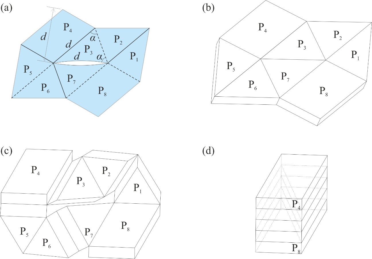
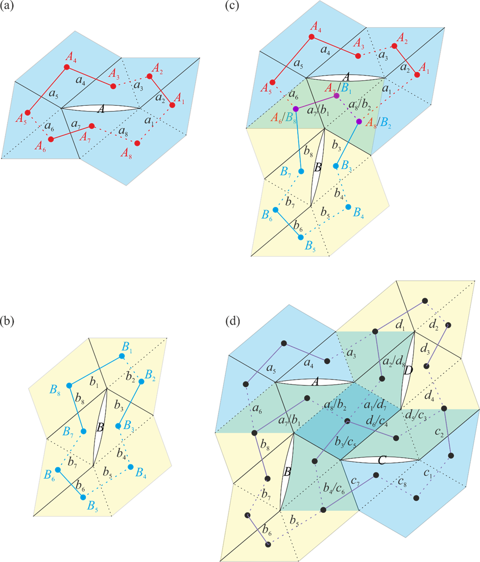
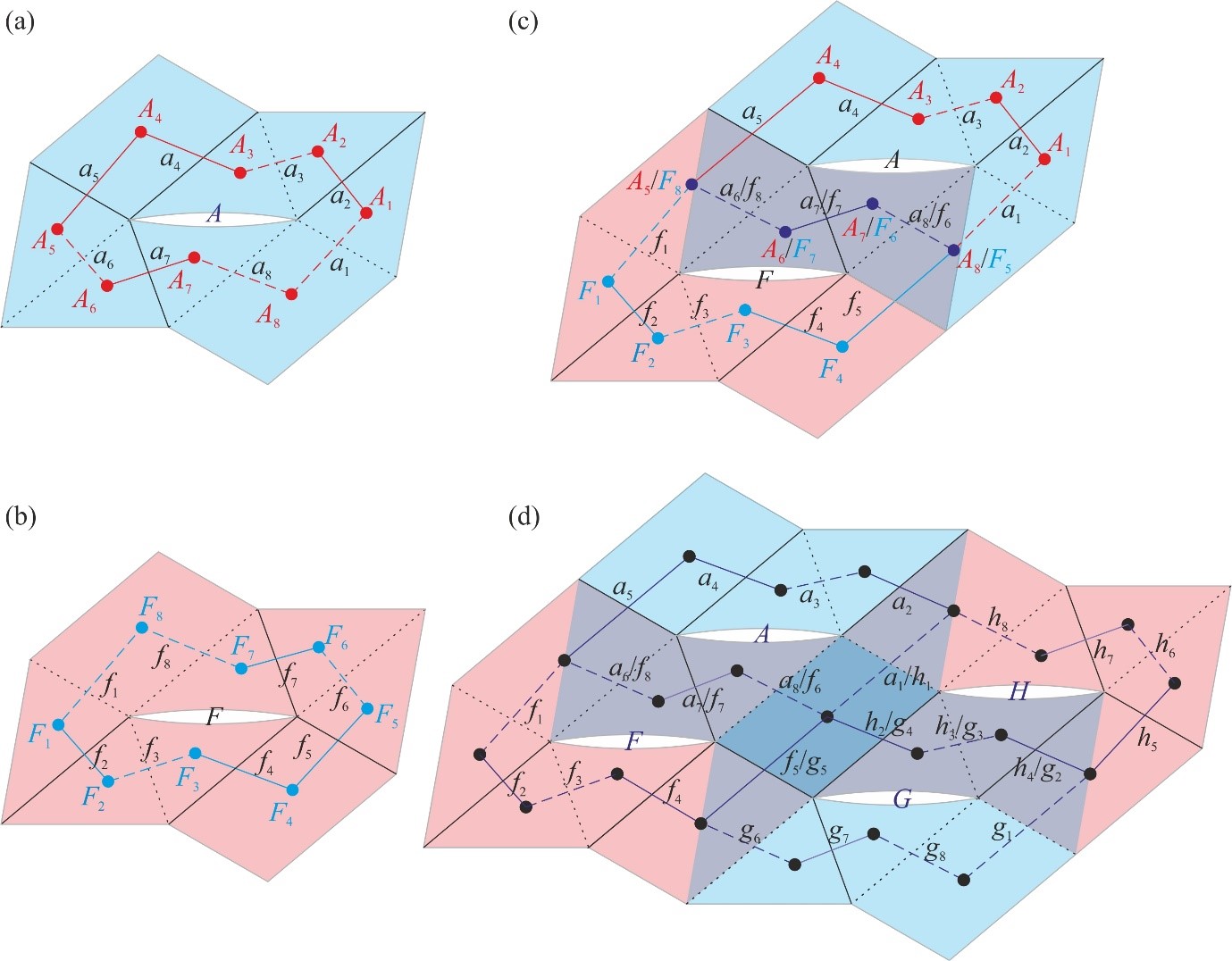
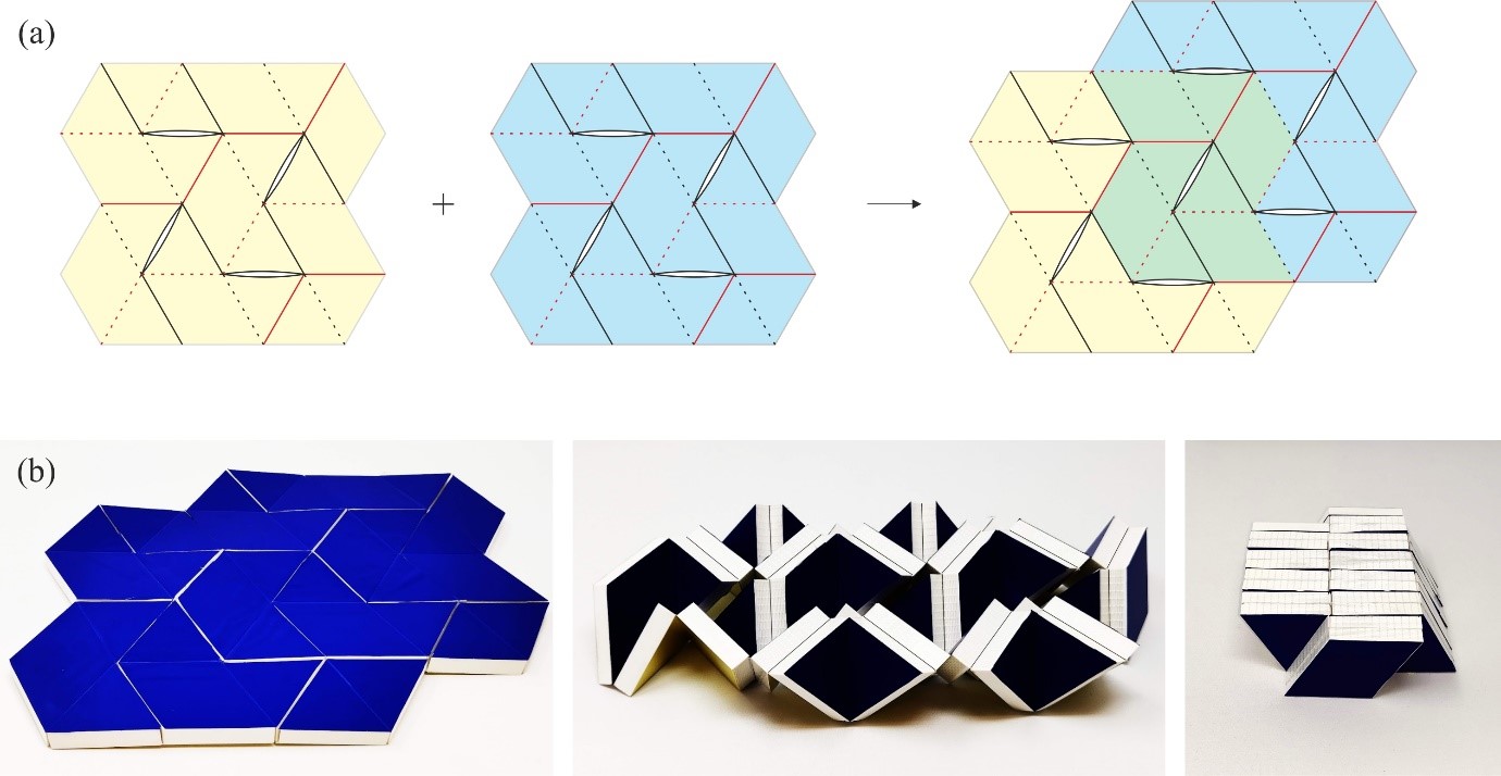
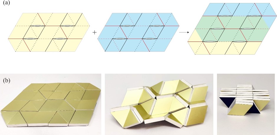
From: Date: 2022-05-22 Flat arrays consisting of panels of finite thickness are widely used in aerospace applications such as solar panels and reflectarray antennas. Packaging them into compact bundles without any voids and then deploying them bi-directionally to flat, continuous, and accurate surfaces with single degree of freedom (DoF) has challenged engineers for decades. Here we present a solution based on origami of thick panels. 1. Thick panel origami based on 8R spatial linkage Consider an origami pattern consisting of six isosceles triangular facets, P1 – P3 and P5 – P7, and two identical parallelogram facets, P4 and P8, as shown in Figure 1(a), in which each parallelogram is a combination of two isosceles triangles. The mountain and valley folds are marked by solid lines and dotted lines, respectively. There is a slit between facets P3 and P7 so that each panel is only connected with two of its neighbours. Converting the facets to panels of uniform thickness yields an assembly shown in Figure 1(b), where adjacent panels are connected by a rotational joint (also known as a revolute joint) whose axis is along either their bottom or top edges for a mountain or valley fold, respectively. The slit between P3 and P7 remains. Since there are a total of eight joints, kinematically this assembly is an 8R closed chain. Note that in the folded configuration, the parallelogram panels P4 and P8 appear at the top and bottom layers of the stack, respectively, whilst all of the triangular panels are sandwiched between panels P4 and P8. This 8R closed chain is the element that can then be used to construct foldable units. Figure 1. (a) An origami pattern of two parallelograms and six isosceles triangles, where d is the equal edge length of an isosceles triangle. (b) Its thick panel counterpart. (c) A partially folded and (d) fully folded 8R assembly. 2. Deployable units The 8R element has, in general, two DoFs. In this section, we shall demonstrate that by connecting them properly, a single-DoF unit can be created. Combining four 8R elements in different topologies, two deployable units can be created, which are hereafter termed unit I and unit II, respectively. Figure 2 demonstrates the formation and connectivity of unit I. In Figure 2(a), a topological graph is plotted on the blue 8R element A to demonstrate the connectivity of panels. Now flipping the blue 8R element horizontally and then rotating it by 2α anticlockwise yields the yellow 8R element B as shown in Figure 2(b). All the mountain folds turn into valley folds after flipping, and vice versa. For instance, the line a1 is a valley fold in A, and it turns into a mountain fold in B after the operations, represented by the line b1. We also create exact copies of elements A and B, and name them as elements C and D, respectively. All four elements can then be connected to form unit I as shown in Figure 2(d) where the green panels, including the parallelogram panel at the centre, are formed by merging those overlapping ones. Note that in unit I, all mountain and valley folds remain as they are in each element. Likewise, unit II can be created by merging joints and panels as shown in Figure 3 in which the darker coloured panels are formed by merging those overlapping ones. After that, we prove that these units have only a single DoF, and they can be folded from a flat array to compact bundles without any voids. Figure 2. (a)-(b) Elements A and B and their topological graphs. (c) Connection of elements A and B with overlapping panels and joints merged. (d) Formation of unit I and its topological graph. Figure 3. (a)-(b) Elements A and F and their topological graphs. (c) Connection of elements A and F with overlapping panels and joints merged. (d) Formation of unit II and its topological graph. 3. Tessellation of unit I and unit II We then show that the units can be tessellated to form larger flat arrays where a single degree of freedom deployment and compact packaging properties are intact (Figure 4a and 5a). A parametric study is carried out, which provides a precise design range that prevents the panels from physical interference during deployment. Physical models were constructed which have successfully validated the concepts (Figure 4b and 5b). Figure 4. Tessellation of units I. (a) Two units I are combined. (b) Folding process of the physical model. Figure 5. Tessellation of units II. (a) Two units II, where the blue one is an inversion of the yellow one, i.e., top and bottom creases are exchanged, are combined. (b) Folding process of the physical model.
Video 1 Our work is directly applicable to the design of future flat arrays which can be controlled with ease. The single-DoF deployment considerably reduces control complexity, and the revolute joints amongst the panels are one of the simplest but most reliable mechanical connections. Although slits are introduced in the tessellation to facilitate folding, they are closed in the fully deployed state, leading to a flat, continuous and accurate surface on both top and bottom sides. Besides, the work is also important in the theory of mechanisms. The units are one of the examples where a kinematic loop consisting of linkages of multiple DoFs ends up with single DoF. Other combinations may be possible. We hope that our work could strike further research interest in mechanical and aerospace engineering communities on this type of unusual mechanism.
J. Yang, X. Zhang, Y. Chen, Z. You, Folding arrays of uniform-thickness panels to compact bundles with a single degree of freedom, Proc. R. Soc. A, (2022), 478: 20220043. |
